Tampilkan postingan dengan label INVERTER. Tampilkan semua postingan

25W LOW POWER INVERTER CIRCUIT SCHEMATIC DIAGRAM

25W LOW POWER INVERTER CIRCUIT SCHEMATIC DIAGRAM

The first section of the 555 timer is wires as an astable oscillator with R2 and C1 setting the frequency. The output is available at pin 5. The second section is wired as a phase inverter. That output is available at pin 9. Resistor R3 and R4 keep output transistor Q1 and Q2 from loading down the oscillator.

The two transistors drive the transformer push-pull fashion. When one transistor is biased-on, the other is cut-off. The transformer is a 120V/18V center tapped that is connected backwards, so that is steps the voltage up rather than down. Oscillator circuit U1, R1, R2 and C1 operates from about 4 to 6V with very stable output.

BASIC THEORY of DC to AC INVERTERS CIRCUIT SCHEMATIC DIAGRAM

BASIC THEORY of DC to AC INVERTERS CIRCUIT SCHEMATIC DIAGRAM
This document will show you the basic theory of DC to AC inverters, about the circuit’s works, the calculation to build DC to AC inverter and more. The sample of inverter circuit diagram also included in this document.

CIRCUIT 300W INVERTER DC 24V TO AC 220V SCHEMATIC DIAGRAM

CIRCUIT 300W INVERTER DC 24V TO AC 220V SCHEMATIC DIAGRAM

This is 300W inverter circuit that can convert 24VDC become 220VAC.

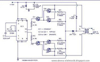
CIRCUIT 100 WATT INVERTER 24VDC TO 220VAC II SCHEMATIC DIAGRAM

CIRCUIT 100 WATT INVERTER 24VDC TO 220VAC II SCHEMATIC DIAGRAM
Built based on IC CD4047 and Mosfet IRF540, this inverter have ability to supply electronic device -which require 220VAC- up to 100w from 2-3A transformer.

CIRCUIT 50W INVERTER 12VDC TO 220VAC SCHEMATIC DIAGRAM

CIRCUIT 50W INVERTER 12VDC TO 220VAC SCHEMATIC DIAGRAM
convert 12V DC to 220V AC dan handle about 50Watt small electronic appliance.
Component List
R1=10Mohms
R2=100ohms
R3=1.2Kohms
R4=560Kohms
R5-6=2.2Kohms
R7-8=56 ohms 5W
CX=22pF trimmed capacitor
C1-2=22pF ceramic
C3=8.2nF 100V MKT

CIRCUIT INVERTER 11W, 12V DC TO 22V AC SCHEMATIC DIAGRAM

CIRCUIT INVERTER 11W, 12V DC TO 22V AC SCHEMATIC DIAGRAM

This is graphic of Inverter 100W, 12V DC to 220V AC. the circuit diagram, is made for electronic browser online.

INVERTER 12V DC TO 240V DC CIRCUIT SCHEMATIC DIAGRAM

INVERTER 12V DC TO 240V DC CIRCUIT SCHEMATIC DIAGRAM
The oscillator circuit consists of a 555 timer connected as an astable multivibrator. The inclusion of D1 ensures that the duty-cycle of the squarewave output is maintained at about 50%. The output of the 555 drives the base of T1 which switches current through one half of the primary of the transformer. T2 is driven from the collector of Tl and thus switches current through the other half of the transformer winding on opposite half cycles of the drive waveform. Zener diodes D4 and D5 protect Tl and T2 from any high-voltage spikes generated by the transformer.

The voltage applied to the transformer primary is stepped up and the required high output voltage appears across the secondary winding. Depending on the application the secondary voltage may or may not be rectified.

CIRCUIT INVERTER 12V DC TO 120V AC SCHEMATIC DIAGRAM

CIRCUIT INVERTER 12V DC TO 120V AC SCHEMATIC DIAGRAM
This is inverter 12V DC to 120V AC. How much this inverter can handle the load depends the transformer.

CIRCUIT BASIC INVERTER SCHEMATIC DIAGRAM

CIRCUIT BASIC INVERTER SCHEMATIC DIAGRAM
Notes:

1. Q1 and Q2, as well as T1, determine how much wattage the inverter can supply. With Q1,Q2=2N3055 and T1= 15 A, the inverter can supply about 300 watts. Larger transformers and more powerful transistors can be substituted for T1, Q1 and Q2 for more power.

2. The easiest and least expensive way to get a large T1 is to re-wind an old microwave transformer. These transformers are rated at about 1KW and are perfect. Go to a local TV repair shop and dig through the dumpster until you get the largest microwave you can find. The bigger the microwave the bigger transformer. Remove the transformer, being careful not to touch the large high voltage capacitor that might still be charged. If you want, you can test the transformer, but they are usually still good. Now, remove the old 2000 V secondary, being careful not to damage the primary. Leave the primary in tact. Now, wind on 12 turns of wire, twist a loop (center tap), and wind on 12 more turns. The guage of the wire will depend on how much current you plan to have the transformer supply. Enamel covered magnet wire works great for this. Now secure the windings with tape. Thats all there is to it. Remember to use high current transistors for Q1 and Q2. The 2N3055's in the parts list can only handle 15 amps each.

3. Remember, when operating at high wattages, this circuit draws huge amounts of current. Don’t let your battery go dead.

4. Since this project produces 120 VAC, you must include a fuse and build the project in a case.

5. You must use tantalum capacitors for C1 and C2. Regular electrolytics will overheat and explode. And yes, 68uF is the correct value. There are no substitutions.

6. This circuit can be tricky to get going. Differences in transformers, transistors, parts substitutions or anything else not on this page may cause it to not function.

other circuit